If you work on real-time systems think embedded controllers, industrial automation, robotics, or sensor-driven applications you know that timing and state behavior aren't optional details. They're the core of how the system works. A single missed transition or an unhandled state can cause failures that range from annoying to dangerous. That's exactly why using a PlantUML state machine diagram to model real-time system behavior is worth your time. It gives you a clear, version-controllable way to define every state, every trigger, and every transition your system must handle.
PlantUML lets you write diagrams as plain text, which means your state machines live right alongside your code in Git. No clunky diagramming tools, no out-of-date image files floating around. You write the syntax, PlantUML renders the diagram. For real-time systems where behavior must be precisely specified and reviewed by teams, that matters a lot.
What does a state machine diagram for a real-time system actually look like in PlantUML?
A real-time system typically has clearly defined operating modes and strict rules about how it moves between them. In PlantUML, you describe these using states, transitions, and events. Here's a straightforward example modeling a real-time temperature controller:
@startuml
[] --> Idle
Idle --> Heating : temp < setpoint
Heating --> Cooling : temp >= setpoint + threshold
Cooling --> Idle : temp <= setpoint
Heating --> Error : sensor_fault
Cooling --> Error : sensor_fault
Error --> Idle : reset
Error --> [] : shutdown
@enduml
This diagram captures the exact conditions under which the controller changes behavior. Each arrow is a guarded transition something happens (a temperature reading, a fault signal) and the system responds. You can find more detailed code variations for state machine diagrams in our PlantUML code examples for state machines.
Why use PlantUML instead of a drag-and-drop diagram tool?
For real-time systems, your diagrams need to stay in sync with the actual system design. That's hard when diagrams are images stored separately from the code. With PlantUML:
- Your state machine definition is plain text, so it lives in version control and shows up in pull request diffs.
- Engineers who don't have Visio or Lucidchart licenses can still read and edit the diagram.
- You can generate diagrams automatically as part of a build or documentation pipeline.
- Reviewers can comment on specific transitions directly in code reviews.
This is especially valuable when you're working with safety-critical or real-time embedded software where traceability between requirements and design artifacts is often required by standards like IEC 61508 or ISO 26262.
How do you model concurrency in a real-time state machine?
Many real-time systems aren't just one state machine they're several running in parallel. A motor controller might have separate state machines for speed regulation, fault handling, and communication. PlantUML supports this with concurrent states using the -- separator:
@startuml
[] --> Active
state Active {
[] --> Running
Running --> Paused : pause_cmd
Paused --> Running : resume_cmd
--
[] --> Normal
Normal --> Faulted : fault_detected
Faulted --> Normal : fault_cleared
}
Active --> Off : power_down
@enduml
The two regions inside Active operate independently. The motor runs or pauses while the fault monitor is either in Normal or Faulted. This kind of concurrent state modeling is common in real-time architectures and PlantUML handles it cleanly.
What about entry, exit, and do activities in state machine diagrams?
Real-time systems often need to perform actions when entering or leaving a state, or continuously while in a state. PlantUML supports all three:
- Entry actions run when the system enters a state (e.g.,
entry / start_timer) - Exit actions run when leaving (e.g.,
exit / stop_motor) - Do activities run continuously while in the state (e.g.,
do / monitor_pressure)
Here's a snippet showing these in practice:
state Monitoring {
entry / open_valve
do / read_sensors
exit / close_valve
}
These actions map directly to code functions in your real-time firmware. When your diagram shows entry / open_valve, a developer knows exactly which function to call when transitioning into that state. That kind of clarity prevents integration bugs.
How do you handle error states and recovery in real-time systems?
Error handling is where real-time systems diverge most from typical software. You can't just throw an exception and hope for the best. Every fault condition needs a defined state and a defined recovery path. A good state machine diagram makes these paths explicit:
@startuml
[] --> Normal
Normal --> Degraded : minor_fault
Normal --> Critical : major_fault
Degraded --> Normal : fault_cleared
Degraded --> Critical : fault_escalated
Critical --> SafeState : timeout
SafeState --> [] : power_off
Critical --> Normal : manual_reset
@enduml
Notice how there's no way to jump from SafeState back to Normal automatically. That's intentional some recovery paths require human intervention. When your diagram enforces this, the state machine design itself becomes a safety mechanism.
What common mistakes should you avoid when modeling real-time state machines?
Here are issues I see frequently:
- Missing transitions: If a sensor fault can happen in five states but you only handle it in three, your system has undefined behavior. Map every possible event in every state.
- Unreachable states: States with no incoming transitions are dead code in your design. PlantUML won't catch this visually unless you look carefully.
- Too many states in one diagram: A 40-state diagram is unreadable. Use hierarchical states (nested states) to group related behavior, which PlantUML supports natively.
- Ignoring timing constraints: PlantUML doesn't model time directly. If a transition must happen within 50ms, annotate it with a note.
note right: Must complete within 50ms - Forgetting the initial state: Every region needs a
[] --> SomeStateentry point. Missing this causes rendering errors.
If you're also documenting how actors interact with these systems, combining your state diagrams with use case diagrams in PlantUML gives a fuller picture of the system.
How do you connect PlantUML state diagrams to your development workflow?
A state machine diagram only helps if it stays current and gets used. Here's how teams working on real-time systems typically integrate PlantUML:
- Store
.pumlfiles in your repo alongside the source code they describe. - Auto-generate PNG or SVG images during CI builds using the PlantUML JAR or Docker image.
- Embed diagrams in documentation using tools like Sphinx, MkDocs, or Doxygen with PlantUML plugins.
- Use code reviews to validate changes to state machines the same way you review code changes.
- Reference state names directly in code using enums or constants that match the diagram.
This last point is powerful. When your C code has enum { IDLE, HEATING, COOLING, ERROR } and your diagram uses the same names, there's no ambiguity about what each state means. If you're documenting broader system architecture alongside state behavior, our guide on PlantUML class diagram syntax covers how to show the structural side of your system.
Can PlantUML handle complex real-time protocols like MQTT or CAN bus state machines?
Yes. The syntax doesn't care about the protocol it cares about states and transitions. You can model a CAN bus node's state machine for error-active, error-passive, and bus-off states just as easily as a thermostat controller. For protocols with defined state machines (like MQTT's connection lifecycle with CONNECT, CONNACK, PUBLISH, and DISCONNECT), you map the specification directly into PlantUML states.
For reference on UML state machine notation standards, the Object Management Group's UML specification defines the formal semantics. PlantUML follows these conventions closely enough for practical engineering use.
Quick checklist for your next real-time state machine diagram
- ☑ List every state your system can be in no skipping error or degraded modes.
- ☑ Map every event/trigger to every state where it can occur.
- ☑ Define entry, exit, and do actions for states that need them.
- ☑ Use hierarchical states to group related behavior and keep diagrams readable.
- ☑ Annotate timing constraints as notes where PlantUML can't express them natively.
- ☑ Make sure every state is reachable and every state has a defined exit path.
- ☑ Store
.pumlfiles in version control next to the code they describe. - ☑ Match state names in your diagram to enum constants in your implementation.
- ☑ Review state machine changes in pull requests just like code changes.
- ☑ Validate the rendered diagram visually before merging text reviews miss layout issues.
Start by picking one real-time component in your system that has unclear or undocumented behavior. Model its states in PlantUML, commit the file, and share it with your team. You'll find design problems in the diagram long before they become bugs in the hardware.
 Plantuml Sequence Diagram Code Examples and Syntax Guide
 Plantuml Class Diagram Syntax and Implementation Examples
 Plantuml Deployment Diagram Code for Cloud Architecture Examples
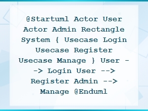 Plantuml Use Case Diagram Code Snippet Examples
 E-Commerce Website Database Schema Diagram Example with Tables and Relationships
 Beginner's Guide to Graphviz Dot Language Syntax