If you've ever tried to sketch out a software system's structure on a whiteboard, you know how messy it gets. Classes overlap, relationships blur, and the eraser runs out before the design makes sense. PlantUML solves this by letting you describe class diagrams in plain text. The syntax is simple enough to learn in an afternoon, but flexible enough to model real-world systems. Understanding how the PlantUML syntax for class diagram implementation works means you can version-control your designs, share them in pull requests, and update them without redrawing anything from scratch.
What does PlantUML class diagram syntax actually look like?
PlantUML uses a straightforward text format. You declare a class with the keyword class, followed by the class name and curly braces for attributes and methods. Here is a basic example:
@startuml
class User {
 - name: String
 - email: String
 + login(): void
 + logout(): void
}

class Order {
 - orderId: int
 - total: double
 + calculateTotal(): double
}

User "1" -- "0.." Order : places >
@enduml
That short block defines two classes with their fields, methods, and a one-to-many relationship. PlantUML renders this into a visual diagram automatically. No drag-and-drop required.
Why do developers use text-based class diagrams instead of drawing tools?
Text-based diagrams fit into existing developer workflows. A PlantUML file lives in your Git repository next to the code it describes. When a class changes, you update the diagram in the same commit. Your team sees the diff. There is no need to export a PNG from a desktop tool, attach it to a ticket, and hope nobody forgets to update it later.
Other reasons developers prefer this approach:
- Version control friendly plain text diffs are easy to review.
- Platform independent PlantUML runs anywhere with Java or an online server.
- Fast iteration changing a relationship is editing one line, not redrawing boxes and arrows.
- Consistent output the layout engine produces clean diagrams every time, regardless of who writes the code.
If you have already worked with PlantUML use case diagrams, the class diagram syntax will feel familiar since it follows the same @startuml / @enduml wrapper pattern.
How do you define classes, attributes, and methods?
A class definition starts with the class keyword. Inside the curly braces, you list members. Each member follows this pattern:
visibility name: typeVisibility markers use standard UML notation:
- + for public
- - for private
- # for protected
- ~ for package-private
Methods include parentheses after the name. You can omit the return type if you prefer a simpler diagram. Here is an example with different access levels:
@startuml
class BankAccount {
 - accountNumber: String
 - balance: double
 # interestRate: double
 + deposit(amount: double): void
 + withdraw(amount: double): boolean
 - validateAmount(amount: double): boolean
}
@enduml
This produces a single class box with a clear separation between the attribute section and the method section, matching standard UML layout conventions.
How do you show relationships between classes?
Relationships are the most important part of a class diagram. PlantUML uses arrow syntax between class names. Here are the common relationship types:
- Association
A --> B(solid line with open arrow) - Inheritance
B --|> A(solid line with triangle arrow, B extends A) - Implementation -
B ..|> A(dashed line with triangle arrow, B implements A) - Composition
A -- B(solid line with filled diamond) - Aggregation
A o-- B(solid line with open diamond) - Dependency
A ..> B(dashed line with open arrow)
You can also add multiplicity and labels. For instance, a university enrollment system might look like this:
@startuml
class Student {
 - studentId: int
 + enroll(course: Course): void
}

class Course {
 - courseId: String
 - title: String
 + getEnrolledStudents(): List
}

class Professor {
 - name: String
 + assignGrade(student: Student, grade: float): void
}

Student "0.." -- "0.." Course : enrolls in >
Professor "1" -- "0.." Course : teaches >
@enduml
The quoted numbers next to the class names define multiplicity 0.. means zero or many. The text after the colon is the relationship label.
Can you use abstract classes and interfaces?
Yes. PlantUML handles both with simple keywords. Mark a class as abstract with abstract class and use interface for interfaces. Methods you want to show as abstract get italic formatting automatically.
@startuml
abstract class Shape {
 + {abstract} area(): double
 + {abstract} perimeter(): double
 + describe(): void
}

class Circle extends Shape {
 - radius: double
 + area(): double
 + perimeter(): double
}

class Rectangle extends Shape {
 - width: double
 - height: double
 + area(): double
 + perimeter(): double
}

interface Drawable {
 + draw(): void
}

Circle ..|> Drawable
Rectangle ..|> Drawable
@enduml
The {abstract} marker renders the method in italic, which is standard UML convention. The extends keyword is a shorthand for the --|> arrow syntax.
What are the most common mistakes when writing class diagram syntax?
After working with PlantUML for a while, you start seeing the same errors repeated. Here are the ones that trip people up most often:
- Forgetting the @enduml tag. Every diagram must be wrapped in
@startumland@enduml. Missing the closing tag produces a parsing error with no helpful message. - Using wrong arrow direction. The arrow points from the source to the target.
A --> Bmeans A has a relationship to B, not the other way around. Swapping them flips the semantics. - Mixing up composition and aggregation. Composition (
--) means the child cannot exist without the parent. Aggregation (o--) means it can. Using the wrong diamond changes the meaning of your entire model. - Overcrowding a single diagram. Putting 40 classes in one diagram makes it unreadable. Split large systems into multiple diagrams organized by module or layer.
- Ignoring stereotypes. Stereotypes like
<<entity>>or<<service>>add useful context. You can add them right after the class name:class UserService <<service>> {
How do you organize complex diagrams with packages and notes?
Large class diagrams benefit from grouping. PlantUML supports package declarations to cluster related classes:
@startuml
package "Domain Model" {
 class User
 class Order
 class Product
}

package "Services" {
 class OrderService
 class PaymentService
}

package "Repositories" {
 class UserRepository
 class OrderRepository
}

OrderService --> OrderRepository : uses
OrderService --> Order : manages
UserRepository ..> User : persists
@enduml
You can also add notes to clarify design decisions:
note right of OrderService
 Handles order lifecycle.
 Delegates payment
 to PaymentService.
end note
Notes render as yellow sticky boxes attached to the referenced class. They help when someone else reads your diagram months later.
What formatting options make class diagrams more readable?
PlantUML offers several ways to control the visual output:
- Hide empty members add
hide empty membersafter@startumlto hide the attribute and method section boxes when they are empty. - Skin parameters use
skinparam classAttributeIconSize 0to remove field/method icons and show cleaner text. - Colors and styling apply
#colorafter a class name to set background color:class Order #LightYellow - Stereotype styling define styles for stereotypes globally:
skinparam classFontColor #333 - Direction control use
left to right directionto change the layout from top-down to left-right, which works better for wide diagrams.
These small adjustments matter when your diagram goes into documentation that others will read. A clean diagram communicates faster than a cluttered one.
How does class diagram syntax compare to sequence diagrams?
Class diagrams show structure what exists and how things relate. Sequence diagrams show behavior how objects interact over time. You typically start with class diagrams during the design phase and add sequence diagrams for specific interactions once the structure is settled.
Both use the same PlantUML toolchain, so your team can maintain all diagrams in one repository with consistent tooling.
Where can you render PlantUML class diagrams?
You have several options for turning your text into images:
- PlantUML online server paste your code at the official PlantUML server and get an instant diagram.
- VS Code extension the PlantUML extension previews diagrams directly in your editor.
- IntelliJ IDEA plugin JetBrains IDEs have PlantUML integration for inline previews.
- Command line run
java -jar plantuml.jar diagram.pumlto generate PNG or SVG output. - CI/CD pipelines generate diagrams as part of your build process and publish them with your documentation.
What are the next steps to get started?
The best way to learn the syntax is to model something you already understand. Pick a small system a blog platform, a todo app, a shopping cart and write the class diagram from scratch. Start with three or four classes and one or two relationships. Render it. Then add more detail.
Here is a practical checklist to follow:
- Pick a system you know well and list its main classes.
- Write each class with its key attributes and methods.
- Define the relationships using the correct arrow syntax.
- Add multiplicities to show how many instances are involved.
- Group related classes into packages if the diagram has more than eight classes.
- Render the diagram and check that the layout makes sense.
- Add notes for any design decisions that are not obvious from the diagram alone.
- Commit the
.pumlfile to your repository alongside the related code. - Review the diagram in your next code review and update it as the design evolves.
For broader reference across different diagram types, explore the full collection of PlantUML code examples for class diagrams to see variations you can adapt to your own projects.
 Plantuml Sequence Diagram Code Examples and Syntax Guide
 Plantuml Deployment Diagram Code for Cloud Architecture Examples
 Plantuml State Machine Diagram Example for Real-Time Systems
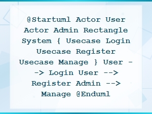 Plantuml Use Case Diagram Code Snippet Examples
 E-Commerce Website Database Schema Diagram Example with Tables and Relationships
 Beginner's Guide to Graphviz Dot Language Syntax